A practical way to check sheet metal flatness in the workshop is to place the sheet freely on a flat reference table and check gaps using a straightedge and feeler gauges. If the steel sheet has repeated waves, record two measurements: the wave height and the distance between consecutive peaks. Whether the part is acceptable depends on the tolerance specified in the engineering drawing or purchase specification.
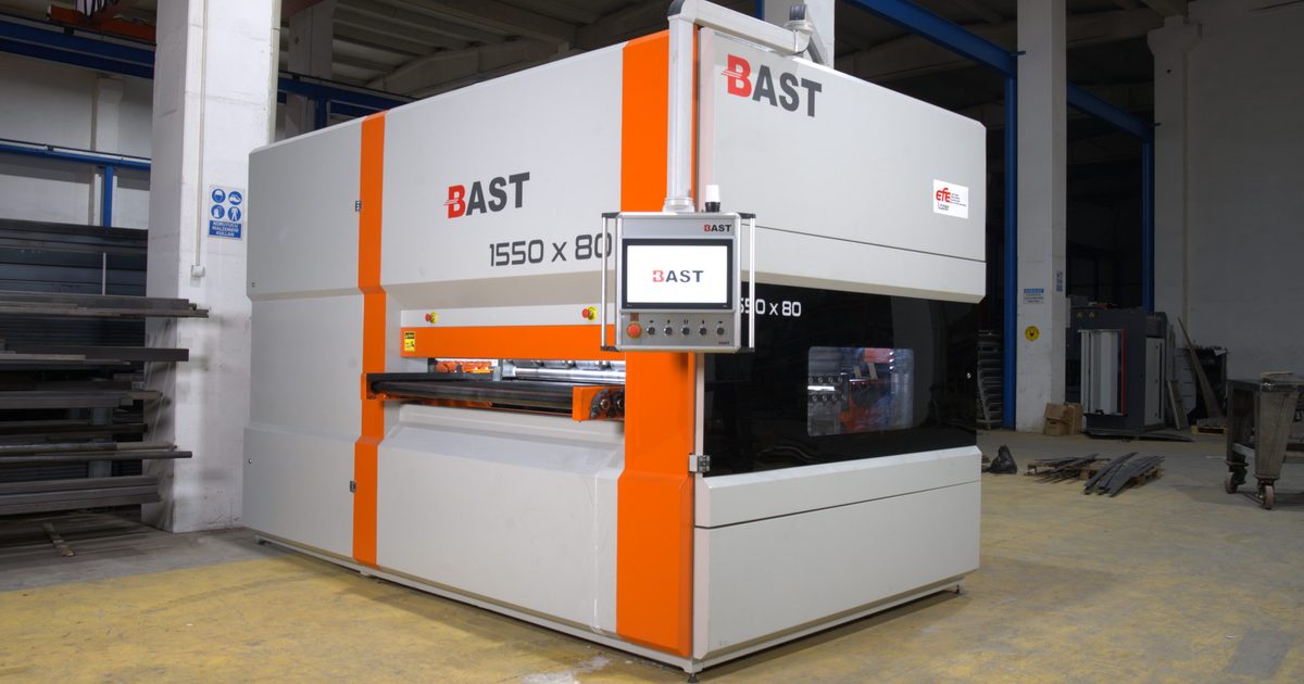
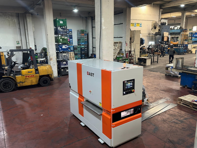
Flatness problems sometimes become apparent only during the next operation. A laser-cut part may develop a raised corner, fail to sit properly against a press brake’s backgauge, or require additional clamping to align two edges in a welding fixture. Measuring the same area before and after cutting helps identify when the problem occurs. Meşe Makina manufactures BAST series roller leveling machines for flattening laser-cut sheet metal parts before bending and welding.
İçindekiler Tablosu
What Is Sheet Metal Flatness?
Flatness describes how far a surface deviates from an ideal plane. Under ISO 1101, when a flatness tolerance is applied to a surface, the entire specified surface must fit between two parallel planes separated by the tolerance value. For example, a 0.5 mm flatness tolerance on an engineering drawing applies to the whole indicated surface. A gap measured at just one corner does not establish whether the entire part meets that requirement.
A sheet with uniform thickness can still have wavy edges. Our article on Automatic Thickness Measurement in Sheet Straightening explains how thickness and flatness measurements serve different purposes in production.
What Types of Flatness Defects Occur in Sheet Metal?
Before measuring, inspect the sheet both lengthwise and across its width. The direction and location of the defect determine how to position the straightedge.
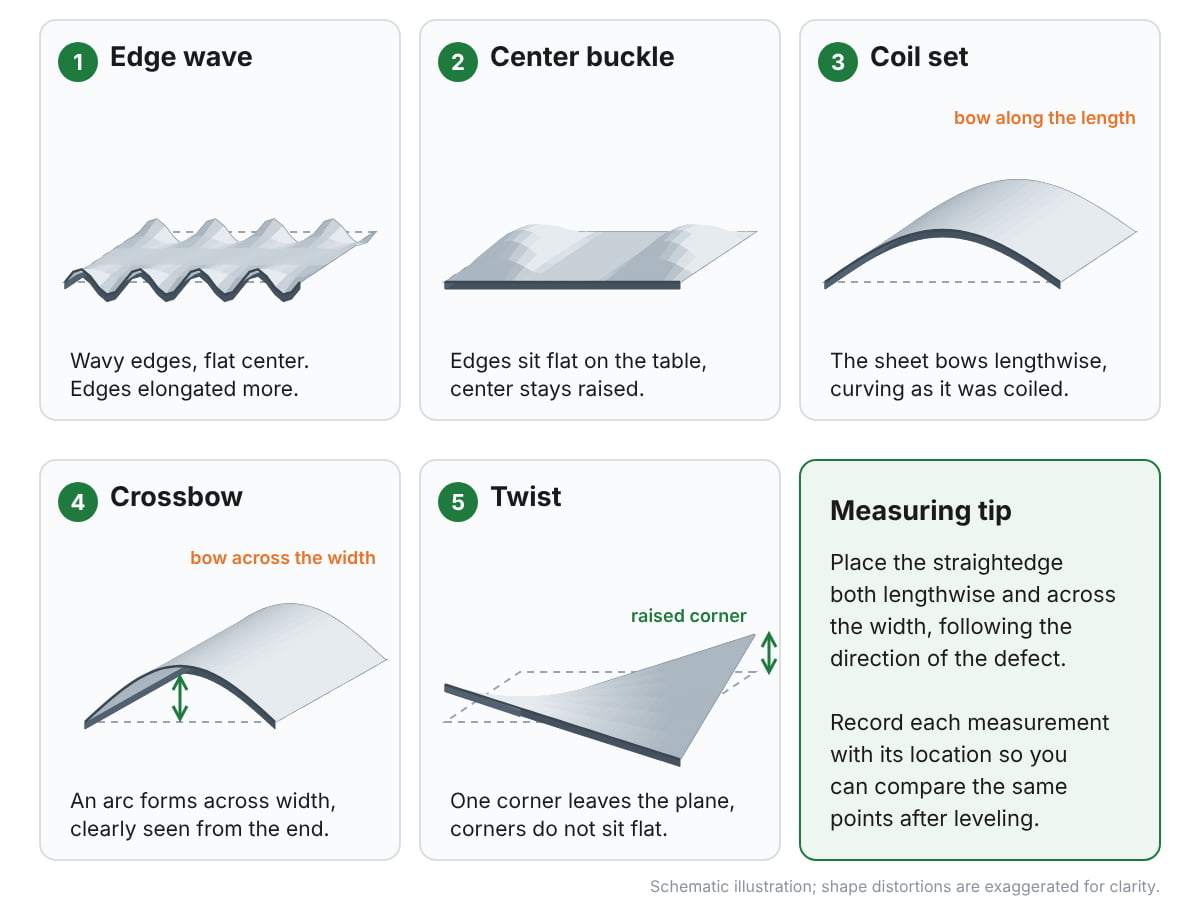
| Defect | How to identify it | Possible cause |
|---|---|---|
| Edge wave | Repeated peaks and valleys appear along one or both edges. | The edges have elongated more than the center during rolling. |
| Center buckle | The edges rest on the table while raised areas remain in the center. | The center has elongated more than the edges. |
| Coil set | Uncoiled material tends to curve back in the direction in which it was wound. | The material retains some of the curvature introduced during coiling. |
| Crossbow | An arc is visible across the width when the sheet is viewed from the end. | Uneven deformation during rolling or leveling. |
| Twist | One end appears rotated relative to the other, and the corners do not all lie in the same plane. | Uneven deformation or residual stresses released during cutting. |
How Is Sheet Metal Flatness Measured?
Checking Gaps with a Reference Table and Feeler Gauges
First, clean the table and the underside of the part. Even a small metal chip can lift a corner and affect the measurement. After placing the sheet on the table, insert feeler gauge blades into the gap beneath the raised edge, starting with the thinnest. Do not press down on the edge. Record the thickness of the blade that fits with slight resistance without lifting the part.
This check is particularly useful for edges and corners. If the raised area is in the center and the gap underneath cannot be reached from the edge, use a straightedge to check the upper surface.
Measuring Waves with a Straightedge and Ruler
To measure an edge wave, first identify two consecutive peaks along the same edge. Then follow these three steps:
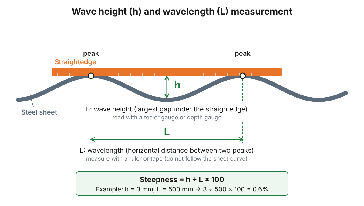
- Rest the straightedge on both peaks. Position it along the direction in which the waves repeat, ensuring that it touches both peaks.
- Measure the wave height (h). Find the largest gap between the underside of the straightedge and the sheet surface between the two peaks. Measure this perpendicular distance using a feeler gauge or a suitable depth gauge.
- Measure the wavelength (L). Use a ruler or tape measure to measure the horizontal distance between the same two peaks. Following the curved sheet surface with the tape will increase the measured length.
If the waves vary along the sheet, repeat the measurements in several areas. Record the height and wavelength of each wave together so that you can compare the same locations after leveling. When evaluating Meşe Makina’s BAST series, these records can provide a practical benchmark for trials with your own parts: what is the height of the same wave after leveling?
Dial Indicators, Lasers, and In-Line Measurement
For small parts, a granite surface plate and dial indicator can be used to record surface heights at different locations. Contact force matters because the indicator tip can deflect thin sheet metal. For large sheets, laser measurement or optical 3D scanning can show where deviations are concentrated on a surface map. A coordinate measuring machine (CMM) can also be used to inspect parts against engineering drawing requirements.
In rolling lines, a shapemeter monitors the tension distribution across the width of the moving strip. This information supports process adjustments during production. The shape of the strip after it has been cut and released from tension can be checked separately.
| Method | Factors affecting measurement accuracy | Speed | Relative cost | Suitable application |
|---|---|---|---|---|
| Reference table and feeler gauges | Table flatness and gauge thickness increments | Fast | Low | Edge and corner checks |
| Straightedge and ruler | Straightedge accuracy and contact locations | Fast | Low | Wave height and wavelength measurement |
| Granite surface plate and dial indicator | Probe force and measurement point spacing | Moderate | Moderate | Small-part inspection |
| Laser measurement or optical 3D scanning | Calibration and surface reflections | Fast | High | Large-surface scanning |
| CMM | Part support and measurement point spacing | Relatively slow | High | Inspection against drawing requirements |
| Shapemeter | Sensor resolution across the width and strip tension | Continuous | High | Rolling-line process monitoring |
How Should Wave Height Be Interpreted?
Imagine an inspection report that states only “3 mm wave height.” If that height occurs over a wavelength of 500 mm, the wave is relatively gradual. If it occurs over 250 mm, the wave is steeper. To compare the two, divide the wave height by the wavelength and multiply by 100. This ratio is called steepness, expressed as a percentage.
For example, if the wave height is 3 mm and the distance between consecutive peaks is 500 mm, the calculation is 3 ÷ 500 × 100 = 0.6%. For a regular, approximately sinusoidal wave, these measurements correspond to roughly 8.9 I-units.
A workshop record such as “3 mm wave height with a 500 mm wavelength along the left edge” clearly identifies both the location and size of the defect. When requesting a quotation from Meşe Makina for a suitable leveling machine, include these measurements along with the sheet thickness, material grade, and required tolerance.
What Flatness Tolerance Is Acceptable for Steel Sheet?
To determine the applicable flatness tolerance, first consider how the product was manufactured and supplied. For example, two hot-rolled products of the same thickness may have different production routes: one may be cut from coil, while the other may be rolled as plate. Different standards may therefore apply.
| Standard | Application |
|---|---|
| EN 10051 | Covers continuously hot-rolled strip and sheet or plate cut from that strip. The delivery form is relevant to the flatness assessment. |
| EN 10131 | Specifies dimensional and shape tolerances for cold-rolled steel flat products for cold forming within its scope. |
| EN 10029 | Applies to hot-rolled steel plates 3 mm thick or above within its scope. It includes normal Class N and special Class S flatness tolerances. |
| ASTM A1030/A1030M | Describes how to measure flatness characteristics of steel sheet products. Acceptance limits are determined by the applicable product specification. |
The purchase specification should identify the applicable standard and the required flatness class, where relevant. During quality control, measured deviations are compared with the conditions specified for the product thickness, material grade, and measurement length. If the engineering drawing specifies a separate tolerance for the cut part, the finished part must be evaluated against that requirement.
What Should You Do If Flatness Is Outside Tolerance?
First, check for burrs or metal chips beneath the part and repeat the measurement. Allow freshly laser-cut parts to cool, and do not press down on raised edges during inspection. Record the batch number, measurement direction, straightedge length, and location of the largest deviation.
If the deviation occurs repeatedly within the same batch, compare measurements taken before and after cutting. When precision leveling is required, consider the material grade, part length, and target tolerance alongside the sheet thickness and width when selecting a machine. The most useful comparison comes from measuring the same points on your own parts before and after leveling.
You can explore Meşe Makina’s roller leveling models and working range diagrams on the BAST Sheet Leveling Machine page.
Frequently Asked Questions
What Is an I-Unit?
An I-unit expresses the relative length difference between different regions of a strip. One I-unit corresponds to a length difference of 0.01 mm over a reference length of one meter.
How Many Millimeters of Flatness Deviation Are Acceptable for Sheet Metal?
The acceptable deviation depends on the product standard, sheet dimensions, material grade, and specified tolerance. To assess a measured gap, you also need to know the length over which it was measured.
Why Does Sheet Metal Distort After Laser Cutting?
When a cut part separates from the surrounding sheet, residual stresses in the material can redistribute. This may cause bending or raised corners, particularly in long, narrow parts. Localized heating during cutting can also contribute to distortion.
What Is the Difference Between Flatness and Parallelism?
Flatness controls the form of a single surface, while parallelism also controls its orientation relative to a specified datum. For example, a part’s upper surface can be flat while still being tilted relative to its lower surface.