
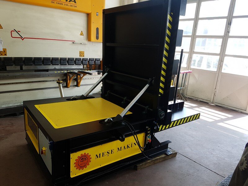
In sheet metal processing facilities, handling heavy coils is often considered a routine material-handling task. However, the nature of the operation changes when a coil is not merely transported but turned from a horizontal position to a vertical position, or vice versa.
This is because the operation changes not only the position of a load weighing several tonnes but also the position of its centre of gravity relative to the axis of rotation. If the coil is not properly supported or its movement is not sufficiently controlled, even a minor error can have serious consequences for employee safety, material integrity and production continuity.
The main question is therefore not simply, “How can we turn the coil?”
The real questions are: How frequently is the turning operation performed, and is a crane attachment still sufficient for the job, or is a controlled coil-upending station now required?
İçindekiler Tablosu
Transporting and Upending a Coil Are Not the Same Operation
When a coil is transported from one location to another by crane, its orientation generally remains unchanged. During upending, however, the coil rotates by approximately 90 degrees.
This is where the critical difference arises. The centre of gravity moves throughout the turning operation. After a certain point, the coil’s own weight begins to accelerate the movement. If this movement is not controlled, stopping the load safely becomes more difficult.
This creates three primary risks:
- Risk to personnel: Operators or nearby employees entering the load’s movement area may be exposed to serious injury.
- Material damage: Uncontrolled contact between the coil and the floor or surrounding equipment may cause crushed edges, deformation of the outer wraps and feeding problems in downstream processes.
- Production and equipment losses: Damaged material, unexpected downtime, extended crane use and damage to nearby equipment directly increase production costs.
Coil upending should therefore be treated not merely as a matter of selecting lifting equipment, but as a separate process-safety issue.
When Is a Crane Attachment Sufficient?
A fixed machine is not required for every coil-upending operation.
If coils are turned infrequently, the operation takes place at different points within the facility, or it is not possible to establish a fixed station, a suitable below-the-hook turning attachment may be a more practical solution.
It is important to distinguish between standard lifting equipment and an attachment specifically designed for turning. Slings and standard C-hooks are primarily used to lift and transport loads. A sling holds the load, but it does not control its rotation. Changing the coil’s orientation in a controlled manner requires the management of different forces and the shifting centre of gravity.
Equipment used for turning should therefore:
- Be suitable for the relevant coil geometry
- Secure and control the load properly
- Have clearly defined capacity and centre-of-gravity limits
- Include appropriate safety systems to prevent the load from disengaging from the attachment
Purpose-designed below-the-hook turning attachments provide a more controlled solution than standard sling arrangements. However, the main limitation remains unchanged: the operation is still performed using the crane.
The crane remains occupied throughout the turning operation, the process depends on crane availability, and the operator continues to play a significant role in positioning accuracy. This may be acceptable if the operation is performed only a few times a month or day. When it becomes a frequently repeated task, however, the method should be reassessed in terms of both efficiency and safety.
When Is a Coil Upender Required?
The main advantage of a fixed coil upender is not simply its ability to turn heavier loads.
The key difference is that it transforms coil turning from a temporary crane-assisted movement into a defined and repeatable process.
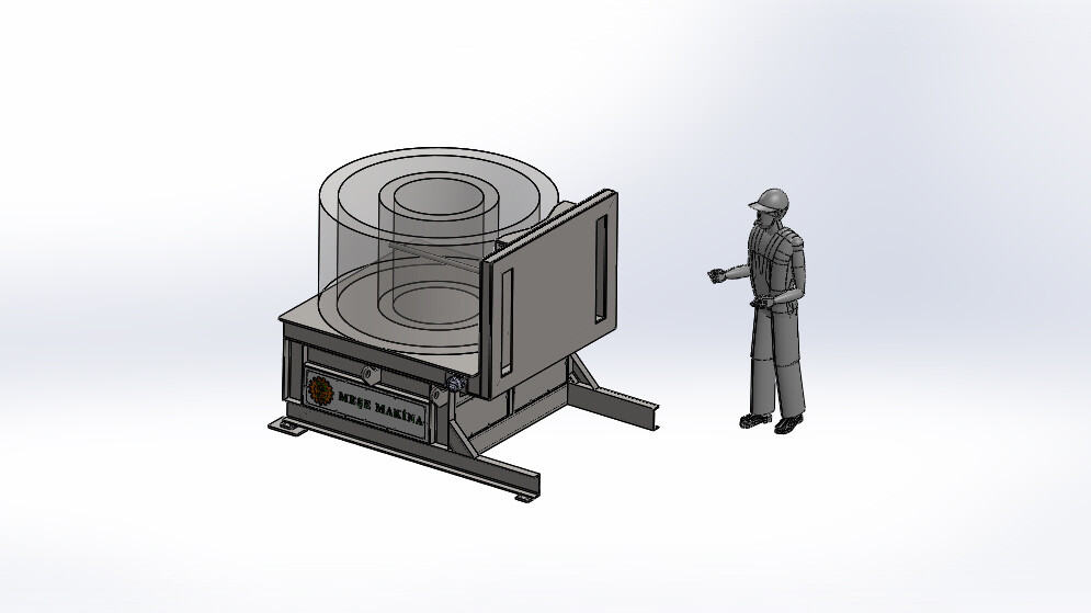
The coil is placed on the machine, which supports the load and turns it along a defined axis. With a properly designed drive system, the load remains under control even as the position of its centre of gravity changes relative to the axis of rotation. This prevents the coil from accelerating under its own weight and moving uncontrollably after passing a certain point.
In practical terms, a coil-turning operation repeatedly performed at the same station is no longer merely an auxiliary handling activity. It has become a regular part of the production flow. At this stage, the objective should be to minimise dependence on operator experience and make every cycle repeatable.
A coil upending and turning machine meets this requirement. The same controlled turning principle can also be applied to dies and marble blocks, with die-turning machines operating on a similar principle.
What Does a Fixed Machine Change?
The Turning Movement Becomes Standardised
In crane-assisted operations, the movement of the load is influenced by the position of the attachment, crane movements and operator intervention. With a fixed machine, the load follows a defined path during every cycle.
This is important not only for safety but also for process quality.
The Crane Is Released for Other Tasks
The crane is used to place the coil on the machine, but the turning operation itself takes place at the fixed station.
This is a significant advantage, especially in factories where a single crane serves multiple production areas. When a crane is occupied solely for coil turning, it creates a loss of capacity that often goes unnoticed because it is not formally recorded.
Operator Interaction With the Load Is Reduced
With the correct station layout and safety systems, the operator can remain outside the hazardous movement area while the coil is being turned.
The position of the control device is not the only consideration; the safety architecture of the entire station must be assessed. Depending on the risk assessment, two-hand controls, light curtains or other area-protection systems may be used. The objective is to control access to the hazardous area and protect both the operator and nearby employees during movement.
The Coil Is Supported More Effectively
Contact surfaces should be designed according to the geometry of the load to prevent damage to the coil edges or outer wraps.
This has a direct effect on scrap costs, particularly in applications where surface quality is critical or edge deformation can disrupt downstream processes.
Mechanical or Hydraulic Coil Upender?
Once a fixed turning station has been selected, the next question is how the movement should be generated.
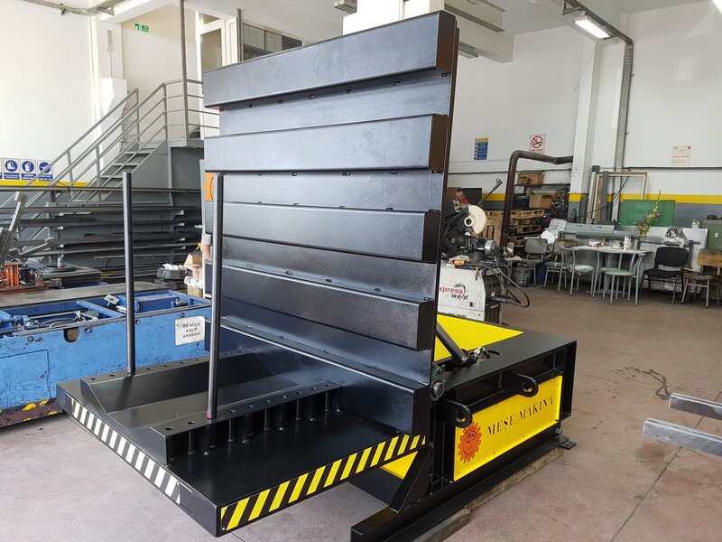
In hydraulic systems, the turning movement is produced by a pump and cylinder assembly. In mechanical systems, movement is provided by a motor, gearbox and suitable power transmission system. Both systems can turn a coil, but their behaviour differs under repetitive production conditions.
For a turning process that operates regularly at the same station, a mechanical solution offers several advantages.
Movement at a Defined Speed
With a mechanical drive, the turning speed is not affected by the load weight, oil temperature or system pressure. The cycle time remains consistent, making it easier to include the turning operation in production planning and synchronise it with the line cycle.
Direct Control of Load Movement
With a correctly selected mechanical drive assembly, movement stops when the drive stops. A self-locking gearbox or brake motor can keep the load in position if power is interrupted.
Because there is no hydraulic pressure-loss scenario, holding the load does not depend on the correct operation of a separate hydraulic safety circuit.
No Hydraulic Oil or Hoses
Eliminating the risk of hydraulic leakage is particularly advantageous in production areas where surface quality is important. Oil dripping onto the floor, additional cleaning requirements and slip hazards are also eliminated.
Simpler Maintenance
Mechanical systems do not require periodic hose replacement, oil analysis or the monitoring of filters and sealing components. Regular lubrication and inspection of the drive assembly are generally sufficient.
Better Suitability for Continuous Operation
At high cycle rates, heat build-up in the hydraulic power unit and the need for cooling may create practical limitations. A mechanical system consumes energy only while it is moving and does not require a continuously operating power unit while idle.
This does not mean that hydraulic solutions are unsuitable. Hydraulic systems may still be appropriate for very high-tonnage applications with a limited range of movement and only a few cycles per day.
However, the requirements change when coil upending becomes a production step repeated throughout the shift. In this situation, a mechanical coil upender is generally the more suitable solution because it provides more consistent cycle times, fewer maintenance requirements and a cleaner working environment.
What Should Be Considered When Selecting a Coil Upender?
It is not sufficient to assess the system solely by asking, “How many tonnes can it handle?”
Coil Geometry
In addition to maximum weight, the minimum and maximum coil diameter, coil width and centre-of-gravity position must be known. The machine should accommodate not only the coils currently used but also foreseeable variations in future production.
Cycle Frequency
A station used only a few times a day should not be designed in the same way as one that operates continuously throughout a shift.
The number of cycles affects many components, including drive selection, gearbox sizing, bearing arrangements and fatigue calculations for the supporting structure. This is why mechanical drives are generally preferred for high-cycle applications.
Control of the Turning Movement
The machine’s ability to rotate by 90 degrees is not sufficient by itself. Particular attention should be paid to how the movement is controlled when the centre of gravity passes the support point.
The key question to ask when obtaining a quotation is:
How does the system maintain control when the coil’s own weight begins to accelerate the movement?
Load-Holding Safety
The load must not move uncontrollably in the event of a power failure or component malfunction.
In mechanically driven coil upenders, this function is provided through the drive assembly and braking system, without the need for a separate pressure-holding circuit.
In a hydraulic coil upender, a suitable load-holding safety function must prevent uncontrolled movement in the event of hose damage or loss of hydraulic pressure.
The specific technical solution will vary according to the system design. The important principle is that a single failure must not result in uncontrolled movement of the load.
Contact Surfaces
The geometry and coating of the surfaces supporting the coil should be suitable for the material being handled. Hard metal contact may leave unacceptable marks on coils with sensitive surfaces or edges that are vulnerable to deformation.
Area Safety
Access to the movement area must be assessed not only for the operator but also for other employees nearby.
The safety solution therefore involves more than a single control button. The machine’s position within the facility, pedestrian traffic and the surrounding working area must all be considered together.
Floor and Layout
The static and dynamic loads of a high-capacity machine are transferred to the facility floor. Floor load-bearing capacity, anchoring or foundation requirements, and the machine’s relationship with the crane route must be assessed during the project stage.
For a fixed machine to provide an operational advantage, it must be installed at a location that supports an efficient coil flow.
A Practical Example: Collaboration With TKG Automotive
The coil upending and turning machine we developed together with TKG Automotive was selected as a “Recommended Practice” in the category for workplaces with 500–1,499 employees at the 2021 MESS Stars of Occupational Safety competition.
The significance of this project lies not only in the machine itself. The solution was developed after analysing the existing operation. Coil geometry, the method used to deliver the load, the facility layout and the occupational safety risks associated with the operation were assessed together.
This also explains why a standard machine cannot be applied in exactly the same way to every facility handling heavy materials. A system suitable for one facility may require redesign for another because of different coil dimensions, crane layouts, floor levels, cycle frequencies or safety requirements.
How Can the Investment Be Justified?
Assessing a coil-upender investment solely on the basis of the equipment price will not provide an accurate result. Three areas should be evaluated together.
Occupational Safety
Does the current operation require employees to enter the load’s movement area? What is the risk rating of the turning operation in the facility’s risk assessment?
If a high-risk operation is controlled only through procedures and operator attentiveness, an engineered solution becomes more appropriate.
Crane Utilisation
How many minutes is the crane occupied when turning one coil, and do other departments have to wait for the crane during this period?
Multiplying this time by the number of daily turning operations reveals the total capacity loss and the potential benefit of a fixed machine.
Material Damage
Are crushed coil edges, deformed outer wraps or line-feeding problems being recorded? If the amount of scrap attributed to the turning operation can be measured, it should be included directly in the investment calculation.
Maintenance and operating costs should also be added to these three factors. The absence of hoses, hydraulic oil and filters in a mechanically driven station can positively affect the long-term return on investment.
When these factors are assessed together, a coil upender becomes more than an occupational safety investment; it also becomes an investment in production continuity and capacity.
A Short Checklist for Your Production Line
- Is coil upending defined as a separate operation in your risk assessment?
- How many times a day are coils turned, and has this number increased in recent years?
- Is the operation always performed at the same location?
- Do other operations have to wait for the crane during coil upending?
- Do employees need to approach the load’s movement area during the operation?
- Was the attachment specifically designed for coil upending, and are its capacity and centre-of-gravity limits known?
- Do you experience damage to coil edges or outer wraps?
- Does the maintenance of your current equipment involve recurring downtime caused by hoses, hydraulic oil or leaks?
- Will the operation need to handle higher capacities or different coil dimensions in the future?
If the answer to several of these questions is “yes”, it is necessary to consider not only whether the current method works, but whether it is still the right method.
Conclusion
Although a crane attachment and a fixed coil upender may appear to be direct alternatives, they are designed for different operating scenarios.
A suitable below-the-hook turning attachment is a logical choice for infrequent operations performed at different locations and requiring a high degree of flexibility. However, if coil upending is repeatedly performed at the same station, regularly occupies the crane and presents a significant occupational safety risk, a fixed turning station becomes the more appropriate solution.
The decision should therefore not be based on the question, “Which equipment is less expensive?”
The real question is:
Is coil upending still an occasional material-handling task in our facility, or has it become a production step that needs to be standardised?
If the second situation applies, a mechanical coil upending and turning machine is more than a piece of equipment that changes the orientation of a coil. It is a process solution that makes the operation more controlled, repeatable, low-maintenance and independent of the crane.
You can explore our heavy-load turning machines and contact us to discuss a solution suited to your coil dimensions, capacity requirements and facility layout.

Leave A Comment